

History
October 28, 2016
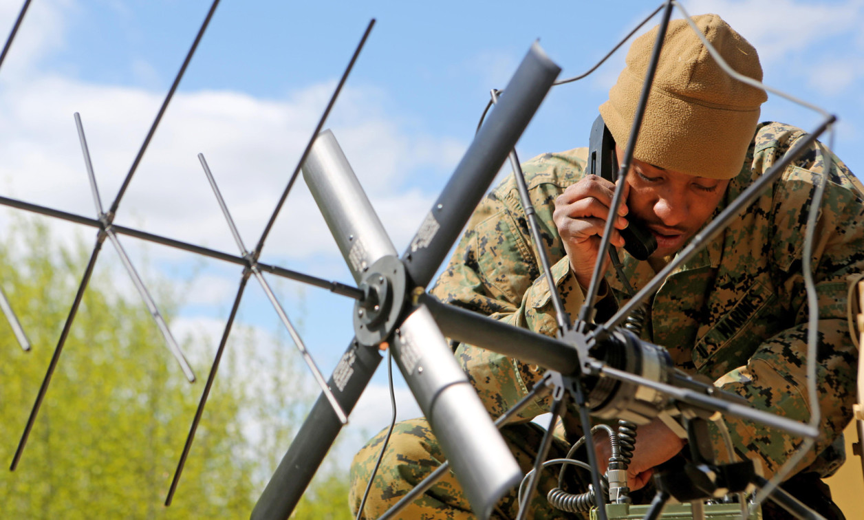
Software Defined Radio (SDR) is not a new technology to the military as it was developed for defense communications. However, it evolved beyond the now obsolete Joint Tactical Radio System (JTRS) program. Although JTRS is no longer an active program, some variants of the system survive, such as the Rifleman radio, MIDS J and HMS Manpack.
The Army needs an improved communications system to enable collaboration, improve information sharing, and facilitate shared situational analysis. This may interest you : The Battlefield That’s 5 KHz Wide. In addition, the military needs a system that is capable of engaging in spectrum jamming and operating synchronized ground and airborne radio networks.
An SDR is a wireless communication device where the modulation/demodulation of the transmitter and receiver is done in software. As a result, functionality is only modified or changed by the software, avoiding the need to make physical changes to the hardware. It also does not require the use of capacitors and resistors, as software-based filtering algorithms can be used to select specific frequencies.
With SDR, algorithms can be both downloaded and adapted throughout the hardware lifecycle. SDR is also capable of incorporating new functionality that allows it to do much more than transmit voice and data.
With the development of SDR technology, it solved the problem of the need for multiple devices to participate in military communication. Since SDR is controlled by software, functions such as encoding/decoding and modulation/demodulation are no longer hardware bound and can be modified by software. These features mean that users can adapt to changes in the environment by making software changes to perform tasks such as changing modulation schemes, frequencies and migration.
SDR is also used to monitor communications on several different frequencies, including VHF, UHF, and HF. Several different protocols – such as CDMA, GSM, Bluetooth, WiFi and LTE – can be managed simultaneously, while combining the ability to monitor a large portion of the spectrum while supporting these protocols. That being said, military SDRs currently face the phase coherence and latency issues of multiple-input/multiple-output (MIMO) systems.
For any application that requires more than one radio chain (eg radar, beamforming, 3GPP (LTE), other cellular environments, MIMO applications), there is a significant challenge in ensuring that there is some phase coherence and time delay.
Achieving true phase coherence between multiple RF signal acquisition channels requires that all clock signals be shared directly between each ADC and downconverter. However, synchronization becomes easier with a simple down-conversion architecture. (Figure 1.)
Figure 1: Clock Allocation Architecture.
|
|

Systems that use single-stage down-conversion or direct down-conversion (zero-IF) include fewer local oscillators (LOs). Most of the time LO signals can be shared directly between down converters. In many cases, LO signals can be shared directly between buck converters, making phase-coherent measurements possible.
Consider the following scenario, which involves the synchronization of four receiver circuits set up as a direct-conversion quadrature receiver. The LO can be obtained from a built-in oven-controlled crystal oscillator (OCXO) or it can be taken from an external source. In the case of the latter, a common LO may also be shared between two or more separate units. Additionally, the OCXO can provide a common reference output for use in some applications.
The OCXO provides a very stable (± 5ppb) signal that can be tuned using the nanoDAC. The source is then buffered to provide two outputs (one for an external reference clock and one as the primary output for the internal system) where the primary output goes to an ultra-low noise clock divider and delay that allows phase shift/group capabilities for delay. After the divider, the output goes to the first low jitter clock generator in the system.
The default clock conditioner has a 10MHz input and uses the internal Phase Locked Loop (PLL1) to drive a 100 MHz VCXO with low phase noise. This locks the extremely low 100MHz phase noise VCXO to the stability provided by the 10MHz input. The 100 MHz VCXO output subsequently drives PLL2 of the first clock conditioner. This provides 322 MHz JESD204B (subclass 1) device clock and sysref clock to the converters and transceivers (ADC, DAC and FPGA).
A buffered copy of the 100 MHZ VCXO output is also provided to a second clock, via a second clock divider. The buffered output drives the second PLL of the second divider and provides synchronization of all frequency synthesizers for each front channel. (Figures 2 and 3.)
As a result, this default configuration allows some (in-phase) deterministic relationship for all outputs.
Figure 2: and Figure 3: Transmit radio architecture (top) and receive radio architecture (bottom) demonstrating high-frequency and baseband stages.
|
|

All that is required is a limited knowledge of DSP techniques and phase-coherent down-conversion, which can be used to explore complex methods for the calibration of a phase-coherent measurement system.
This can be achieved by using a vector signal generator connected to the system and a power divider. Since all RF front-ends will be tuned to the same center frequency, the measurement system can be calibrated easily by analyzing each of the down-converted waveforms on the analyzer’s baseband.
Baseband sampling, both I and Q, allows direct access to the phase data of an acquired waveform containing both phase and magnitude data. Different software platforms can be used to coordinate the domain and calculate the phase information of each sample. This is done by calculating the arctangent of Q/I.
Two important tasks can be accomplished by monitoring the phase data from an IQ waveform: First, fine adjustments can be made to the initial phase of each NCO by measuring the phase information, which then compensates for the variation in cable length for both analysts. Calibration only needs to be done once to remove residual distortion.
The Crimson TNG SDR platform from Per Vices has designed the clock distribution to provide a multi-channel transceiver capable of providing deterministic phase coherence and latency. Its four independent receive circuits and four independent transmit circuits are capable of up to 322 MHz RF bandwidth up to 6 GHz. (Figure 4.)
Figure 4: The Crimson TNG SDR, in a 1U form factor, is powered by an Altera Arria V FPGA (5ASTMD3E3F31I3N) with an on-chip dual-core ARM Cortex-A9 processor with a web-based interface.
|
|

As a result, when it comes to military SDR, multi-channel phase-coherent RF measurements should no longer be a problem, as today’s modular instrumentation has evolved to meet the new measurement requirements of military communications systems.
Stephanie Chiao is a product marketing manager at Per Vices Corporation, where she is responsible for marketing strategy, technical promotion and media relations. She brings over nine years of consumer and enterprise marketing experience and has worked with brands including Microsoft, Rogers Wireless and Torstar Corporation. She holds a Bachelor of Business Administration with honors from the Schulich School of Business in Toronto. She can be reached at [email protected].
According to vices www.pervices.com
Featured companies

Comments are closed.