
SDR transceiver delivers big advances in frequency hopping – 27 October 2021 – Altron Arrow
SDR transceiver delivers big advances in frequency hopping
27 October 2021
Telecoms, Datacoms, Wireless, IoT
By Mizhou Tan, RF product applications engineer, Analog Devices.
In contrast to conventional radio communications, frequency hopping (FH) defines a method of transmitting radio signals by rapidly changing its carrier frequency and was first mentioned by Nikola Tesla in his 1903 US patent, ‘Method of Signaling.’ Later, in 1942, actress Hedy Lamarr and composer George Antheil further solidified the concept by using a piano roll to change among 88 frequencies to prevent interference to the radio control of torpedoes.
In contrast to conventional radio communications, frequency hopping (FH) defines a method of transmitting radio signals by rapidly changing its carrier frequency and was first mentioned by Nikola Tesla in his 1903 US patent, ‘Method of Signaling.’ Later, in 1942, actress Hedy Lamarr and composer George Antheil further solidified the concept by using a piano roll to change among 88 frequencies to prevent interference to the radio control of torpedoes.
Over the past hundred years, from the non real-time, slow-speed communication between fixed command points in World War I to the real-time, high-speed multimedia communication between aircrafts, ships and land-based systems, FH has arrived at a new era in military applications. In addition to that, FH has been widely adopted in many wireless personal communication networks such as Bluetooth Personal Area Network (PAN), as well as in consumer and hobby radio areas such as walkie-talkies, model cars and drones.
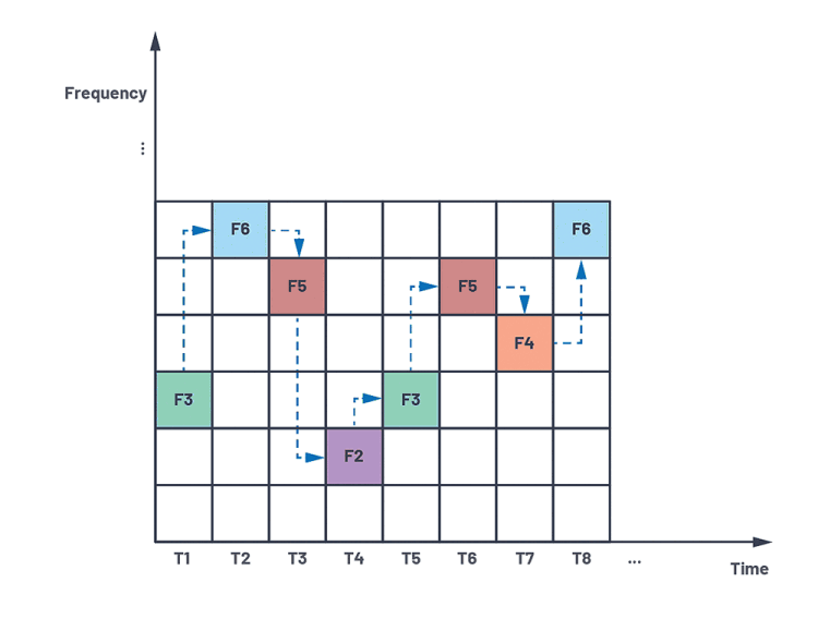
Figure 1. High-level concept of frequency hopping.
What is frequency hopping?
The high-level concept of FH is illustrated in Figure 1. The entire frequency band and time duration are divided into two-dimensional grids. At any given time slot, a different frequency sub-band is utilised for communication. This brings the benefit of high resistance to narrowband interference and strong capability in combating malicious interception and jamming, since the randomness of the hopping pattern equivalently adds another layer of security that is only decodable between the transmitter and receiver.
In addition, FH signals can easily share the bandwidth with other conventional communications due to the minimal mutual interference, resulting in high spectrum efficiency. With an increased hop rate and a larger set of frequency sub-bands, the advantages of FH become more prominent, which makes it an attractive solution for many different applications.
The next-generation SDR transceiver
The ADRV9002 is a dual narrowband and wideband software-defined radio (SDR) transceiver which provides state-of-the-art RF performance as well as advanced system features such as digital predistortion (DPD) and FH. It operates from 30 MHz to 6 GHz and covers the ultra high frequency (UHF) bands; very high frequency (VHF) bands; industrial, scientific and medical (ISM) bands; and cellular frequency bands in narrowband (kHz) and wideband operation up to 40 MHz.
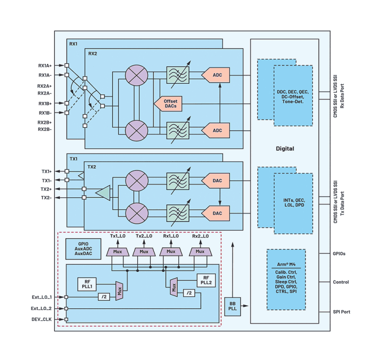
Figure 2. High-level block diagram of the ADRV9002 with flexible PLL design.
Figure 2 depicts a high-level block diagram of the ADRV9002. It includes dual transmit and receive channels with a set of advanced digital signal processing algorithms. The phase locked loop (PLL) structure inside the red dashed box is unique in the sense that instead of having one dedicated PLL for the receive data path and one for the transmit data path as many other transceivers do, two RF PLLs are employed in the device and both can optionally source any receiver or transmitter, or both, or neither.
This flexibility is essential to support FH in various TDD applications such as single-channel and dual-channel operations, including transmit-only mode (1T/2T), receive only mode (1R/2R) and transmit and receive mode (1T1R/2T2R). Both channel diversity and channel multiplexing are supported for the dual-channel operations. Furthermore, two PLLs can be operated in a ping-pong mode to satisfy the stringent FH timing requirement.
Very fast FH with two-PLL muxing and fast PLL retuning
FH is achieved by retuning the PLL before switching to a different frequency.
The ADRV9002 provides different FH modes based on PLL usage. Each time slot in Figure 1 stands for a hop frame, which is divided into a transition time period and a dwell time period, as shown in Figure 3.
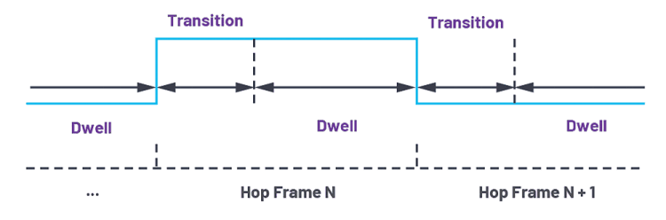
Figure 3. Hopping frame structure.
In a slower FH mode with a sufficiently long transition time (greater than the channel setup time and required PLL tuning time) between frequency changes, only one PLL is needed for a pair of transmit and receive channels in a TDD operation (PLL retune mode).
To achieve faster FH with a shorter transition time (shorter than the channel setup time and required PLL tuning time), two PLLs are employed in the device (PLL mux mode). The two PLLs coordinate with each other in a ping-pong fashion: while one PLL is used for the current frequency, the other PLL is retuned to the next frequency. This makes very fast FH possible and could significantly reduce the required transition time between different frequency changes. These two modes are summarised in Table 1. As shown, the selection of these two modes depends on the transition time the user defines.
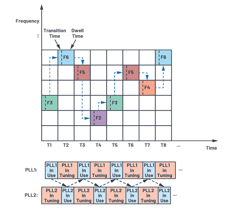
Figure 4. PLL mux mode for fast frequency hopping.
Figure 4 further describes the concept of PLL mux mode. As mentioned earlier, each time slot stands for a hop frame consisting of a transition time period and a dwell time period. While one PLL is used during the dwell time, the other PLL has started tuning from the beginning of the transition time of the same hop frame. It can continue the tuning until the end of the transition period of the next hop frame. Therefore, PLL mux mode is successful as long as the required PLL tuning time is less than the summation of one dwell time plus two transition times.
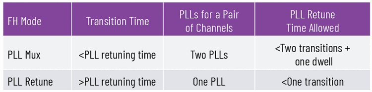
Table 1. ADRV9002 FH mode based on PLL usage.
FH with PLL mux mode is critical for military applications such as Link 16. Link 16 is considered one of the most important tactical data link standards used by the North Atlantic Treaty Organization (NATO) as a jamming-resistant, high-speed digital data link operating in the radio frequency band of 960 MHz to 1,215 GHz.
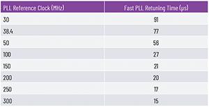
Table 2. PLL retuning time using fast PLL retuning mode
By properly calibrating the entire hop frequency range at the initialisation time, the ADRV9002 employs fast PLL retuning mode to meet the stringent timing requirement. PLL retuning time depends on the ADRV9002 PLL reference clock rate. Table 2 shows the fast PLL retuning time required based on a different PLL reference clock rate. At a PLL reference clock rate of 300 MHz, the fast PLL retuning time is approximately 15 µs. With a hop frame length of 13 µs for Link 16, the 15 µs of PLL retuning time when using PLL mux mode can satisfy the timing requirement if the transition time is greater than 2 µs, as shown in Table 1.
Link 16 message data can be sent as either a single pulse or a double pulse, depending on the packing structure. The single-pulse structure consists of a 6,4 µs on-time and a 6,6 µs off-time with a total duration of 13 µs. The double-pulse structure consists of two single pulses that carry the same data but use different carrier frequencies, as shown in Figure 5. Therefore, the transition time could be 6,6 µs long (>2 µs), which makes Link 16 FH feasible with the ADRV9002.
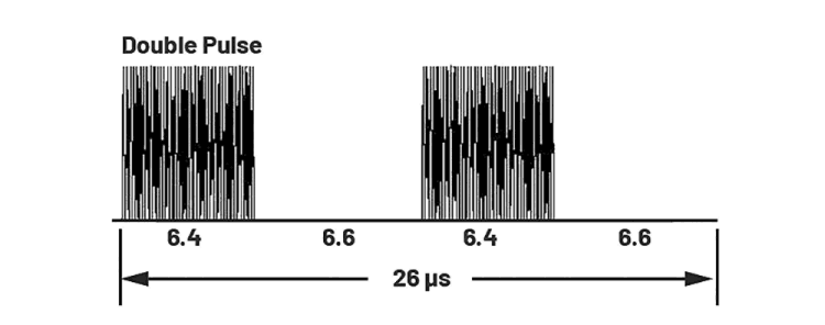
Figure 5. Standard Link 16 double-pulse structure.
Figure 6 shows the ADRV9002 transmit output (power vs. time and frequency vs. time) with Link 16-type hop frames (transmit-only FH is used for simplicity).
Note that in order to show the minimum transition time achievable by the ADRV9002, the experiment does not follow the standard Link 16 pulse structure in Figure 5.

Figure 6. Transmit output for Link 16 Tx frequency hopping.
The on-time is increased from 6,4 µs to 11 µs and the off-time is reduced from 6,6 µs to 2 µs. A Tektronix RSA306B spectrum analyser is connected to the transmit output port on the ADRV9002 evaluation board for observation. The upper plot shows the performance of power vs. time. It can be seen that transmit hopping happens every 13 µs with a transition time of about 3 µs between consecutive transmit hop frames. The lower plot shows the performance of frequency vs. time.
In this experiment, the transmit carrier frequency cycles through four different frequencies in a 1 MHz step size. As expected, the lower plot proves that the transmit output is also cycling through four different frequencies in a 1 MHz step size with good frequency accuracy throughout the entire dwell time.
Further measurements are performed to study the frequency accuracy of the Link 16 FH using more advanced test equipment such as Keysight Technologies’ E5052B and the Rohde & Schwarz FSWP. In the example measurement shown in Table 3, the transmit carrier frequency is hopping at 400 MHz, 400,1 MHz, 400,2 MHz and 400,3 MHz. The transmit input is constructed to produce 400 MHz output for all the hop frames.
The measurement duration is set at 100 µs, which includes seven complete hopping frames. The frequency is measured at every 128 ns time interval. It can be observed that the PLL is fully locked at the beginning of the dwell time. The frequency error during the dwell time depends on the phase noise performance.
Table 3 shows the average, maximum and minimum frequency offset (the absolute difference between the output frequency and 400 MHz) performance for these seven consecutive hop frames. In most frames, the average frequency error is less than 1 ppm. The results are also found to be repeatable for tens of measurements. Note that the measurements could vary depending on the equipment and test configurations.
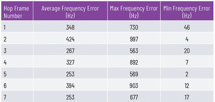
Table 3. Frequency accuracy performance with Link 16 frequency hopping.
The ADRV9002 provides user capability to fine tune the PLL loop filter bandwidth. The performance shown in Table 3 is achieved when the PLL loop filter bandwidth is configured at 1200 kHz. Larger PLL filter bandwidth improves the PLL retuning time, which guarantees the full lock of PLL before the dwell time starts. When selecting the loop filter bandwidth, users should also evaluate the phase noise performance required in their applications.
Static and dynamic table loading of up to 128 different frequency entries
The ADRV9002 utilises a hop table concept for all modes of FH. A hop table contains a list of frequencies and other operation parameters for each hop frame. A hop table can be static, meaning it is loaded during the initialisation and not allowed to change on-the-fly. It can also be dynamic, which means it is loaded while performing the hopping; in such a case, the user can change the table content on-the-fly. A similar concept of ping-pong is employed so that the user can optionally load two different tables, each with a minimum of one to a maximum of 64 entries.
While one table is being used for the current hop frame, the other table is being loaded to prepare for the next hop frame. Each entry notifies the ADRV9002 of the configurations for a certain hop frame. A hop table can be indexed by either incrementing the index automatically (start from the first entry of the first table to the last entry of the second table and then go back to the first entry of the first table again with two hop tables or loop continuously with one hop table) or accessing a specific entry at any time indicated through digital GPIOs.
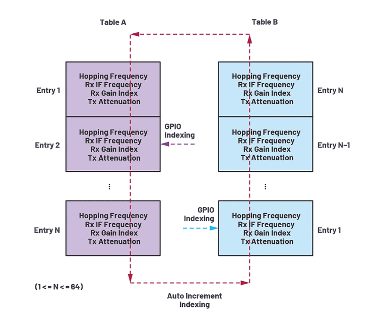
Figure 7. ADRV9002 hop tables content and the indexing method.
Figure 7 shows hop table A and B, each with N entries (1 ≤ N ≤ 64). Each entry in the table includes four key parameters: hop frequency, intermediate frequency (for receive IF mode only), receive gain index and transmit attenuation. In a TDD operation, users must notify the ADRV9002 which channel (either transmit or receive) is enabled for each hop frame by using a dedicated channel setup signal (one for each transmit channel and one for each receive channel). Therefore, although each entry in the hop table contains parameters for both receive and transmit, only the relevant parameters are utilised.
Before further discussing the hop table operation in FH, it is worthwhile to understand the high-level communication between the ADRV9002 and the baseband integrated circuit (BBIC).
As shown in Figure 8, the BBIC acts as the main foundation for FH operation, which sets up FH mode, the channel setup signals (Rx1_ENBALE, Rx2_ENABLE, Tx1_ENABLE and Tx2_ENABLE), the hop signals (HOP1 and HOP2) and the static or dynamic hop tables (hop frequency, receive IF frequency, receive gain and transmit attenuation). The BBIC communicates with the ADRV9002 through an SPI interface or digital GPIOs. The ADRV9002 acts as the node for FH by accepting the signals from the BBIC and then configures the data path and LOs accordingly.
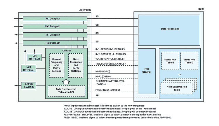
Figure 8. A high-level block diagram of communication between the ADRV9002 and BBIC during frequency hopping.
An example of a dynamic table loading with only one frequency per hop table (A and B) is described in Figure 9. This is an extreme case that allows users to change the hop frequency every frame on-the-fly. PLL mux mode is utilised in this example. As shown in Figure 8, both the rising and falling edges of the hop signal define the timing boundaries of a hop frame, each consisting of a transition time and a dwell time as mentioned earlier. The channel setup signal rising edge defines the type of hop frame that follows a one-frame delay (this delay is necessary for PLL mux mode).
Note that the channel setup signal could stand for either the transmit setup signal or receive setup signal. Figure 9 shows a simplified version of the signal.
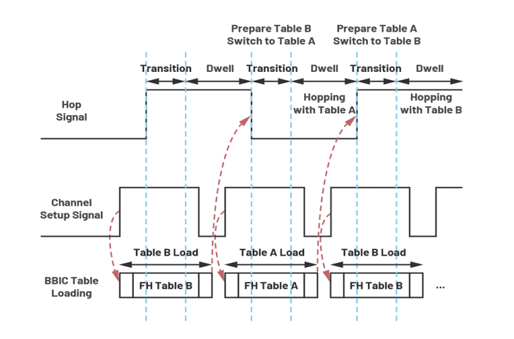
Figure 9. An example of dynamic table loading with one frequency per table using PLL mux mode.
Because TDD operation involves both transmit and receive, users need to configure both the transmit setup signal and receive setup signal separately.
In addition to indicating the hop frame type, the channel setup signal can also be used to trigger the loading of a hop table initiated by the BBIC. The hop table loading should be completed before the hopping signal edge after the channel setup signal falling edge and then the PLL starts tuning to this frequency at the same hop edge and becomes ready for the next hop frame signalled by the next hop edge. Table A and Table B operate in a ping-pong mode so that, after loading is complete, FH operates on the frequency of one table while the frequency of the other table is being tuned.
Figure 10 presents the transmit frequency vs. time output with dynamic table loading for four entries per load and eight entries per load. The transmit input has four frames at 0 kHz, -100 kHz, -200 kHz and -300 kHz frequencies respectively and it is fed to the ADRV9002 by looping the frames continuously. It is also fully aligned and synchronised with hop frames so that the 0 kHz input frame aligns with 3,1 GHz LO. During FH, when LO changes to the next frequency, the transmit input frequency also changes to the next frequency.
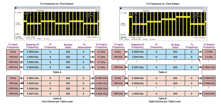
Figure 10. A comparison of dynamic table loading with four entries per loading and eight entries per loading.
Table A and Table B are dynamically loaded while performing FH (for simplicity and easy observation, the table content does not change from load to load). For four entries per load, we expect to see four consecutive transmit output frames at 3,1 GHz and then four consecutive frames at 3,1004 GHz and the same pattern repeats again and again. For eight entries per load, we expect to see four consecutive transmit output frames at 3,1 GHz, four consecutive frames at 3,1004 GHz, four consecutive frames at 3,1008 Hz and four consecutive frames at 3,1012 GHz and the same pattern repeats again and again. The transmit output shown in Figure 10 proves that the dynamic table loading works as expected.
Channel diversity vs. channel multiplexing using dual channels
As shown in Figure 2, the ADRV9002 supports dual transmit and receive channels. FH can be applied on both channels to achieve either channel diversity or channel multiplexing.
For diversity, both channels are hopping simultaneously by using the same PLL (either one or two) and the same hop tables and TDD timing configurations. The multichip synchronisation (MCS) capability provided by the ADRV9002 could be enabled to ensure that multiple channels on the same or different ADRV9002 devices are fully synchronised with each other with deterministic latency. Phase synchronisation can also be achieved through MCS, which is performed each time the PLL retunes frequency.
With MCS, multiple channels could achieve synchronicity even during FH, making the ADRV9002 an attractive solution for MIMO diversity applications involving FH. For channel multiplexing, each pair of channels uses one PLL and performs FH independently from each other. One limitation is that the very fast FH, which requires two PLLs for a pair of transmit and receive channels, can’t be applied for channel multiplexing with one ADRV9002 device.
Besides 2T2R mode, it is worth mentioning that the ADRV9002 also supports 1T2R and 2T1R operations for FH, which provides greater flexibility to meet users’ specific requirements.
Support of FH with DPD operation
The ADRV9002 also supports DPD operation for both narrowband and wideband applications. It corrects the nonlinearity of the power amplifier (PA) to significantly improve PA efficiency while achieving standards-compliant adjacent channel power leakage ratio (ACPR) performance.
One advanced feature of the ADRV9002 is that DPD can be performed together with FH. In such a case, the ADRV9002 allows users to configure up to eight frequency regions and the DPD algorithm creates an optimal solution for each frequency region. A DPD solution as a set of coefficients can also be stored and loaded at the end and the beginning of a transmission, respectively, for each region. This ensures PA linearity for the entire hop frequency range.
Since DPD is an adaptive filtering process that must capture a set of samples periodically for coefficient computation, the hopping frame length needs to be sufficiently long to satisfy the DPD capture length requirement. However, in cases when users only utilise the initially loaded DPD coefficients without the need for DPD updates, this restriction can be removed.
ADRV9002 tracking calibrations are usually not performed during fast FH. However, the initial calibrations are performed based on multiple frequency regions according to users’ FH configurations to achieve the best possible performance.
FH performance evaluation using ADRV9002 transceiver evaluation software (TES)
FH performance can be evaluated thoroughly through the ADRV9002 TES with an evaluation board – both the Xilinx ZC706 and ZCU102 FPGA boards are supported by TES. As shown in Figure 11, the FH configuration pages are easy to use to configure FH parameters, including FH operation mode, the hopping tables, the GPIO setting, the TDD timing, etc. FPGA synchronisation features are built into the TES to allow users to accurately control the TDD timing so that the transmit or receive frames can be fully synchronised with hop frames. Many FH examples are also provided in TES for users to further explore.
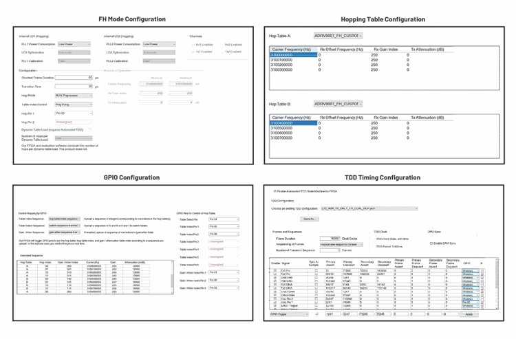
Figure 11. Configuring FH through TES.
Conclusion
FH is one of the advanced system features provided by the next-generation SDR transceiver, the ADRV9002. With two PLLs, multiple FH modes and flexibility in loading and indexing hop tables, the ADRV9002 empowers users with great FH capabilities to handle various applications and achieve advanced system requirements. All features can be thoroughly evaluated through the ADRV9002 TES and software development kit (SDK).
For more information contact Conrad Coetzee, Altron Arrow,
Credit(s)
Comments are closed.