

History
08 October 2015

The pace of technological innovation, along with improvements in component technology and amplifier design techniques used in the commercial wireless industry, have a strong impact on military Software Defined Radio (SDR) requirements.
With commercial cellular technology accounting for more than two billion mobile phones per year and millions of high-power infrastructure access points (base stations, repeaters, microcells, picocells), the mobile phone industry not only meets our personal connectivity needs, but also it’s how it connects our homes, cars and devices. To see also : Ukraine receives first tranche of USD 2.7 billion financial aid from IMF – ThePrint. Three major trends in the cellular industry are directly applicable to the SDR needs of defense electronics: the increase in spectrum used by the device, the increase in waveform bandwidth, and (considering these first two innovations) the ever-increasing need to improve the energy efficiency of radio frequencies (RF).
The range of the spectrum increases
Commercial wireless technology follows reports and specifications created by the telecommunications organization partnership known as the Third Generation Partnership Project (3GPP). The 3GPP standards, called Long-Term Evolution (LTE) and LTE-Advanced, have become the most rapidly deployed and adopted commercial wireless technologies in history. The 3GPP group plans the progress of LTE technology and reports guidelines for the use of frequency bands through phased releases on an almost annual basis. Looking at the progress, 3GPP version 12 demonstrated an increase from 11 operating bands (3GPP version 8) to 44 bands in the last four years. These frequency bands are being coordinated between national spectrum authorities, international guidelines and wireless service providers to meet the growing demand of the commercial industry. Some field designs of popular smartphones address more than 24 lanes. LTE technology is used between 450 MHz to 3.8 GHz today, and with the exploration of LTE-U (unlicensed) technology, we may see the deployment of LTE technology reaching 6 GHz in the near future.
The impact of the wide spectrum coverage within the small form factor of a cell phone or smartphone is that the RF front-end electronics must become scalable and operate over a much wider bandwidth. Six-band phone designs five years ago may have included separate RF paths for transmit and receive bands that contained RF filters and amplifier combinations. These individual radio frequency paths are relatively narrow bands that use a relatively small fractional bandwidth. For example, a frequency duplex bandwidth of 60 MHz at 2 GHz covers requires an RF design to cover only 3 percent of the partial bandwidth of operation. At the component level, narrowband filters and amplifiers can be designed for optimal performance in these very specific bands.
With smartphone designs now operating in dozens of frequency bands, the scalability of narrowband RF designs is no longer practical. Consider an extreme example of a design that can operate in all 44 frequency bands of the Release 12 spectrum range. This would require the RF design to cover over 88 percent of the partial operating bandwidth versus the 3 percent partial bandwidth of the band method. While digital tunable filter technology does not yet meet the basic cost and performance requirements to meet this trend in commercial designs, RF amplifier technologies have already adapted to the wide fractional bandwidth for use in many commercial designs. Filtering technologies such as Surface Acoustic Wave (SAW) and Bulk Acoustic Wave (BAW) have made enormous technical advances in terms of size and cost to remain cost effective for relatively narrow partial bandwidth and low power filter requirements.
Cellular infrastructure technology has experienced a similar challenge. To keep pace with cellular multiband, cellular base station design drivers are innovating higher power technologies. For higher power infrastructure applications covering wide frequency ranges, advances in gallium nitride (GaN) have now led to commercial power transistors that are designed for broadband performance with high power density.
In relation to the defense electronics industry, manufacturing a cost-effective RF front end for tactical radios has always been a challenge. Although no longer a program, the traditional design objective of the Joint Tactical Radio System (JTRS) was to focus on radio waves in the frequency spectrum between 2 MHz and 2 GHz. The operating frequency spectrum, power and performance requirements of the various JTRS radio waves were a major technical barrier to the program. Newer radio programs seek more modest integration requirements.
Consider a current tactical multiband radio that currently operates between 30 MHz and 400 MHz. Tactical VHF support will use the spectrum from 30 MHz to 88 MHz, air traffic control VHF between 118 MHz to 137 MHz, marine VHF between 156 MHz to 174 MHz and military UHF aeronautical radio and between 225 MHz to 400 MHz. A new requirement could take this existing tactical radio and add an integration requirement for Civil First Response Network Authority (FirstNet) Band 14 in the upper 700 MHz frequency band. Since the 10 Watt output power requirement of the Band 14 radio is similar to the power output of some of the other VHF and UHF radios, the integrated design may consider an architecture similar to that widely used in the industry for commercial GaN-based cellular infrastructure with shared RF amplifier design component to reduce the size and weight of the radio.
The GaN industry has used components from major vendors that now support more than 10 watts of power between 30 MHz and 2.5 GHz for tactical radio applications. This is over 98 percent partial bandwidth from a single RF amplifier.
Broadband waveforms
While LTE technology has a maximum signal bandwidth of 20 MHz, LTE-Advanced technology from 3GPP Release 10 saw the introduction of carrier aggregation and carrier aggregation in disjoint spectrum, which increased the data rates delivered over the network. Although the individual channel carrier is still limited to 20 MHz, if you look at the carrier aggregation scenarios shown in Figure 1, the RF signal bandwidth increases dramatically. The continuous two-carrier in-band signal scenario shown in Figure 1a can have up to 40 MHz of output, while the in-band uncoupled configuration in Figure 1b can have full spectrum bandwidth (up to 75 MHz). Furthermore, the interband configuration shown in Figure 1c between two separate bands can have several hundred MHz or even over 1 GHz band separation.
Figure 1: Carrier aggregation scenarios for increased data rates: a) in-band, continuous; b) intra-band, non-adjacent; and c) interband, non-adjacent.
(Click on graphic to enlarge)
|
|
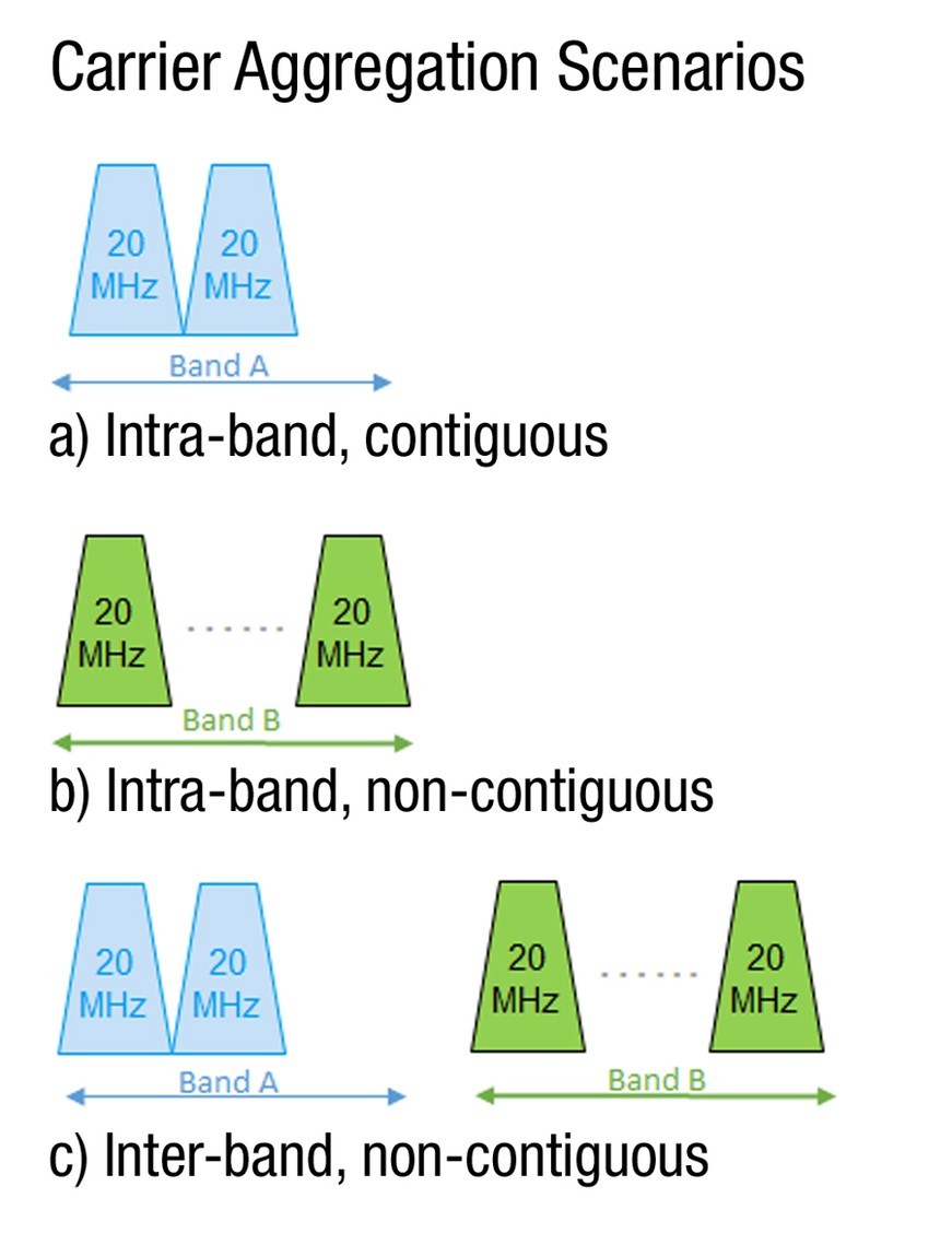
The interband, non-adjacent scenario results in the requirement for both a low-power mobile phone and a higher-power base station, creating essentially one multi-signal waveform across the entire operating bandwidth. The filtering and power amplifier requirements to create this signal continue to be the main drivers of improvements in component technology and amplifier design.
In the tactical radio environment, wideband waveforms are common and have been in field use for many years. Take, for example, the Link-16 radio, which operates in the Aeronautical Radionavigation Services (ARNS) band from 960 MHz to 1215 MHz: this radio covers 255 MHz of the spectrum using frequency hopping and covers over 20 percent of the partial operating band.
Improving RF efficiency
As cellular phone technology improves functionality, increases data rates, increases RF bandwidth, and improves the size and quality of graphic displays, one of the main drivers in the cellular industry is the continued focus on improving the RF efficiency of devices. In mobile phones, improved efficiency enables advanced functionality and longer battery life, but in the cellular infrastructure industry, improved efficiency impacts the bottom line for the wireless service provider by reducing network operating costs. In both cases, the cellular industry has led to improvements in the efficiency of RF devices.
When you consider RF power efficiency in the context of increasing the fractional operating bandwidth and signal bandwidth mentioned earlier, both mobile phone design and cellular infrastructure are moving towards using modulated bias designs for envelope tracking (ET). (Figure 2.)
Figure 2: Block diagram and waveform for envelope tracking.
(Click on graphic to enlarge by 1.9x)
|
|
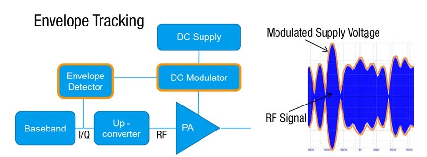
In an ET design, the envelope of the modulated signal is RF matched through the power amplifier by using an envelope detector and a DC modulator controlling the supply voltage. By precisely timing and matching the amplifier’s nonlinear performance, the power amplifier can reach optimal efficiency when operating close to the saturation points of the devices themselves.
Operating a component near saturation requires an analysis of the nonlinear behavior of the device, which may vary due to the RF waveform and power level. Digital predistortion is commonly used to compensate for nonlinear effects and improve spectral purity.
Since the power amplifier can be used in a very large fractional bandwidth, the power supply industry has improved the ability of the amplifier components to operate in these larger bandwidths. Since the signal of interest uses more bandwidth than the amplifier, whether it is a frequency-hopping signal or a multiband signal, it is important to select an envelope detector and DC modulator that have sufficient bandwidth to match the wideband signal . The timing and shaping of the deflection modulation must be carefully characterized. Envelope tracking designs are now common in the cellular industry, and some amplifier designs have over 50 percent efficiency.
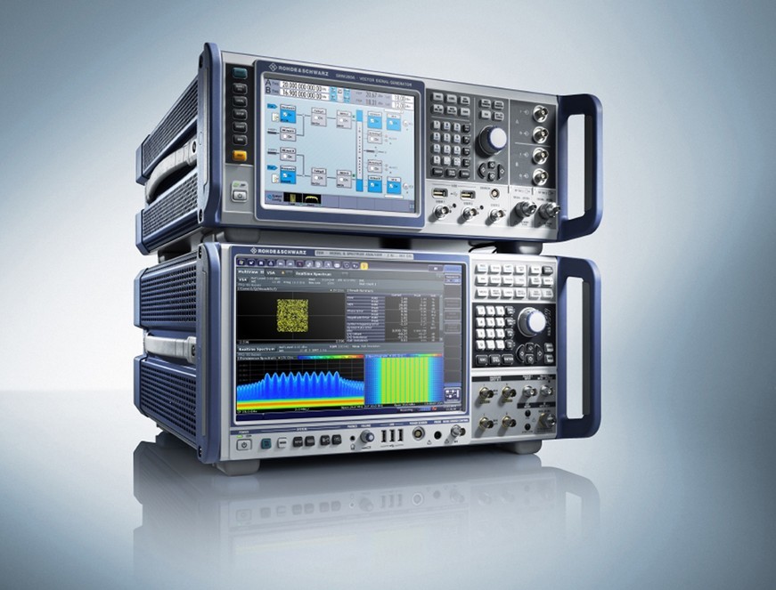
The Rohde & Schwarz FSW signal and spectrum analyzer and SMW signal generator (Figure 3) are aimed at designers and developers of newer envelope tracking designs directly applicable for use in SDR.
Figure 3: The R&S FSW signal and spectrum analyzer and the R&S SMW signal generator perform receiver tests, transmitter tests and envelope tracking projects for designers of software-defined radios.
(Click on graphic to enlarge by 1.9x)
|
|
Darren McCarthy is an aerospace and defense technical marketing manager for Rohde & Schwarz America. He has worked intensively in various test and measurement positions for more than 25 years. He also represented the US as a technical advisor and working group member for eight years on several IEC technical committees and working groups on international electromagnetic compatibility standards. R&S in several industry associations. Darren holds a BSEE from Northwestern University in Evanston, Illinois. Readers can find it at [email protected].
Rohde-Schwarz www.rohde-schwarz.com
Featured companies


Comments are closed.